The content of this category identifies all 7-Bar and 3-Bar ECM currently approved by the DDESB for new construction. Notes are provided to identify those ECM that have NEW limitations and/or restriction associated with their approval.
Select a drawing number to view and download files associated with that ECM.
These documents are available in the following formats:
Adobe Acrobat (PDF) | CAD in compressed ZIP | DWG
| Description | Drawing Number | Dimensions (Internal) |
Door Opening | Weight NEW |
|---|---|---|---|---|
| RC Box Type 'M' | 10400001 through 10400027 Under Navy Review. Contact NAVFAC LANT, Code CI42 |
81'-0" Wide x 124'-0" Long x 24'-6" (Min.) High (Measured at interior face at each side wall). | (2) 14'-0" Wide x 14'-0" High | 350,000lb |
Approved Files for UseDigital DrawingsDocumentationComments/Design ConsiderationUnder Navy Review. Contact NAVFAC LANT, Code CI42 The design provides for internal magazine access by rail and truck. This drawing number represents the most recent design of three versions of the Box Type M Magazine that has been constructed. The initial design was approved by DDESB-KO memo of 9 Apr 93 for construction at NAVWPNSTA Seal Beach. The two subsequent design variations were approved by DDESB-KO memo of 1 Dec 99, for construction at NAVYPNSTA Yorktown. All new construction of Box Type M ECM will be in accordance with drawings 10400001 through 10400027. 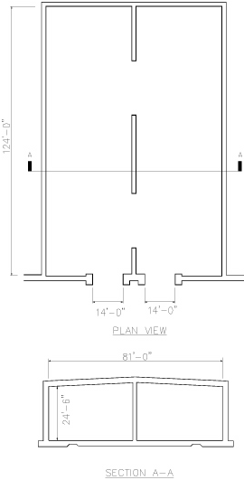 |
||||
| RC Box Type 'C' | 14115934 through 14115968 | 94'-8" Wide x 50'-0" Long x 13'-8" (Rear) To 15'-10" (Front) High | (3) Sliding 26'-6" Wide x 12'-0" High |
500,000lb |
Approved Files for UseComments/Design ConsiderationThese drawings represent the most recent design of Box Type C earth covered magazine, approved by DDESB on 14 October 2022. All new construction of Box Type C magazines will be in accordance with drawings 14115934 through 14115968. |
||||
| RC Box Type 'D' | 14084162 through 14084201 | 158'-8" Wide x 50'-0" Long x 13'-8" (Rear) To 15'-10" (Front) High | (5) Sliding 25'-0" Wide x 11'-0" High |
500,000lb |
Approved Files for UseComments/Design ConsiderationThese drawings represent the most recent design of Box Type D earth covered magazine, approved by DDESB on 17 October 2022. All new construction of Box Type D magazines will be in accordance with drawings 14084162 through 14084201. |
||||
| Navy Modular Storage Magazine | 14115969 through 14116021 | 25'-0" Wide x 80'-0" Long x 14'-8" high | (1) Sliding 25'-0" Wide x 14'-8" high |
500,000lb |
Approved Files for UseComments/Design ConsiderationThese drawings represent the most recent design of Modular Storage Magazine (MSM), approved by DDESB on 13 October 2022. All new construction of MSM's will be in accordance with drawings 14115969 through 14116021. |
||||
| RC Circular Arch | 1404310 through 1404324 Under Navy Review. Contact NAVFAC LANT, Code CI42 |
25'-0" Wide x 80'-0" Max. Length x 11'-11" (Rear) High | (1) Sliding 10'-0" Wide x 10'-0" High or 16'-0" Wide x 10'-0" High |
500,000lb |
Approved Files for UseDigital Drawings
Comments/Design ConsiderationUnder Navy Review. Contact NAVFAC LANT, Code CI42 Superseded NAVFAC's original (1954) Standard Drawings 627954 thru 627957, 649602 thru 649605, 658384 thru 658388, 724368, 751861, 764596 thru 764597, 793746 thru 793748, 803060, and 822978 thru 822989. 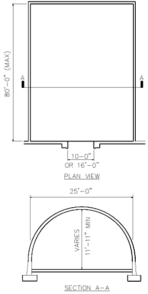 |
||||
| Composite Circular Arch | 1404375 through 1404389 Under Navy Review. Contact NAVFAC LANT, Code CI42 |
25'-0" Wide x x 80'-0" Max. Length x 13'-2" (Rear) High | (1) Sliding 10'-0" Wide x 10'-0" High or 16'-0" Wide x 10'-0" Wide |
500,000lb |
Approved Files for UseDigital Drawings
DocumentationComments/Design ConsiderationUnder Navy Review. Contact NAVFAC LANT, Code CI42 Composite circular arch design composed of an internal 10 gage (0.138 inch) corrugated steel arch with reinforced concrete overlay. Each door is a single piece sliding door. 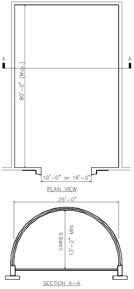 |
||||
| Composite Oval Arch | 1404390 through 1404398 Under Navy Review. Contact NAVFAC LANT, Code CI42 |
28'-2" (Max.) Wide x 20'-0" Min. to 80'-0" Max. Length x 15'-2" (Max.) High | (1) Sliding 10'-0" Wide x 10'-0" High |
500,000lb |
Approved Files for UseDigital Drawings
DocumentationComments/Design ConsiderationUnder Navy Review. Contact NAVFAC LANT, Code CI42 Composite circular arch design composed of an internal 10 gage (0.138 inch) corrugated steel arch with reinforced concrete overlay. Each door is a single piece sliding door. 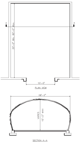 |
||||
| RC Box Type 'E' | 1404523 through 1404537 Under Navy Review. Contact NAVFAC LANT, Code CI42 |
94'-8" Wide x 50'-0" Long x 13'-8" (Rear) To 15'-10" (Front) High | (3) Sliding 16'-0" Wide x 11'-0" High |
500,000lb |
Approved Files for UseComments/Design ConsiderationUnder Navy Review. Contact NAVFAC LANT, Code CI42 DDESB approval signature of 30 June 87 on drawings. 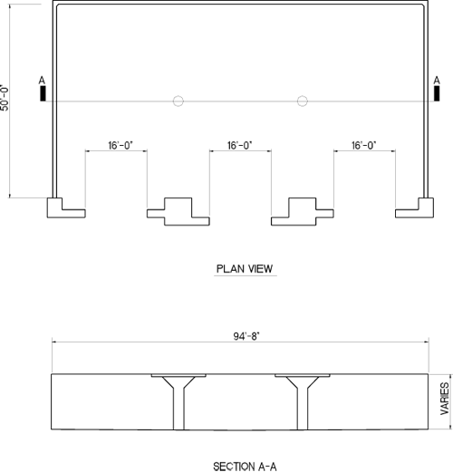 |
||||
| RC FRELOC Stradley | (Korean Version) 33-15-74 |
25'-0" Wide x 87'-0" Max. Length (normally length is 60' or 80') x 13'-0" (Rear) High | (1) Sliding 10'-0" Wide x 10'-0" High |
500,000lb |
Approved Files for UseComments/Design ConsiderationThis design is the latest approved version of the Republic of Korea Army (ROKA) drawing for 33-15-74. The original basis for the Korean version was U.S. Army COE 33-1-74. The Korean drawings assure that all reinforcing steel is electrically continuous. The previous version of this drawing was approved by the DDESB as a 7-bar magazine on 25 May 2002.  |
||||
| RC FRELOC Stradley | (Modified Korean Version) 33-15-74 |
25'-0" Wide x 87'-6" Max. Length (normally length is 60' or 80') x 13'-0" (Rear) High | (1) Sliding 10'-0" Wide x 10'-0" High |
500,000lb |
Approved Files for UseComments/Design ConsiderationThis design is a modified version of the Republic of Korea Army (ROKA) drawing for 33-15-74. The original basis was U.S. Army COE 33-1-74. The Korean drawings assure that all reinforcing steel is electrically continuous. The Modified version includes provisions for air conditioning the magazine. The original version of this drawing was approved by the DDESB as a 7-bar magazine on 25 May 2002. 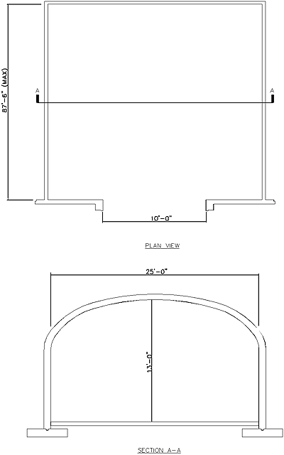 |
||||
| Steel, Semi-Circular Arch | 421-80-01 Under Army Review, Not Approved for New Construction |
Approx. 26'-0" Wide x 19'-0" Min. expandable up to most commonly used 89'-0" Length x 14'-0" (Max.) High | (1) Sliding 8'-0" Wide x 8'-0" High or 10'-0" Wide x 10'-0" High |
500,000lb |
Approved Files for UseNone at this time. Comments/Design ConsiderationUnder Army Review, Not Approved for New Construction If a steel arch ECM is required, use standard drawings 421-80-03, Steel Oval Arch. Contact HNC and USATCES for additional guidance on appropriate site adapt of the 421-80-03 standard. 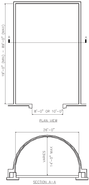 |
||||
| Steel Oval Arch | 421-80-03 | 28'-2" (Max.) Wide x 21'-0" Min. to 89'-0" Max. Length x 14'-11" (Max.) High | (1) Sliding 8'-0" Wide x 8'-0" High or 10'-0" Wide x 10'-0" High |
500,000lb |
Approved Files for UseComments/Design ConsiderationReplaced 33-15-73. Arch design composed of a 1 gage (0.280 inch) corrugated steel arch. The site-adapt Designer of Record shall ensure DoD and Army explosives safety requirements for Lightning Protection and Grounding are met. The Designer of Record shall obtain review support and technical concurrence of the site-adapt design from the U.S. Army Corps of Engineers Engineering and Support Center, Huntsville. 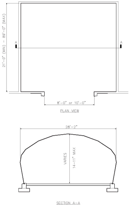 |
||||
| RC Arch | 421-80-05 | 26'-7 1/4" Wide x 90'-0" Max. Length (normally length is 60' or 80') x 14'-0" (Rear) High | (1) Sliding 8'-0" Wide x 8'-0" High or 10'-0" Wide x 10'-0" High |
500,000lb |
Approved Files for UseDigital Drawings
DocumentationComments/Design ConsiderationConstructed using the Techspan Precast Concrete System, developed by the Reinforced Earth Company, for each construction. The headwall and door are derived for 33-15-74. 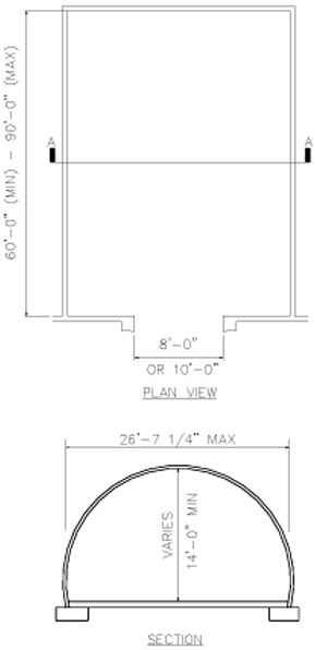 |
||||
| RC Box | 421-80-07 | 25'-0" Wide x 20'-0" Min. to 80'-0" Max. Length x 11'-0" High | Hinged 24'-0" Wide x 10'-4" High |
500,000lb |
Approved Files for UseDigital Drawings
DocumentationComments/Design ConsiderationMSM Standard 421-80-07 replaces the previous MSM Standard 421-80-06 (modified). The new series updates the drawings to meet current AEC CAD standards, improved plan readability, constructability, and correct omissions within the construction drawings. Another key element performed during the revision was the incorporation of lessons learned from previous MSM projects at various user organizations. In addition to the drawings, a conventional structural load analysis was performed to identify some key loading limits, which will assist the designer during the site-adaption process. 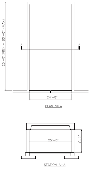 |
||||
| Modular Storage Magazine, Box-Type | 421-80-08 | 25'-0" Wide x 20'-0" Min. to 80'-0" Max. Length x 14'-8" High | Hinged 24'-0" Wide x 13'-11" High |
500,000lb |
Approved Files for UseDigital Drawings
DocumentationComments/Design ConsiderationThe MSM Box-Type Standard 421-80-08 replaces the previous Munitions Storage Magazine (14 feet ceiling height) as designed for Hill AFB. The new series updates the drawings to meet current AEC CAD standards, and features improved plan readability, constructability, and corrects omissions within the construction drawings. Another key element performed during the revision was the incorporation of lessons learned (see Appendix of Design Narrative) from previous MSM projects at various user organizations. In addition to the drawings, a conventional structural load analysis was performed to identify some key loading limits, which will assist the designer during the site adaption process. 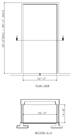 |
||||
| ECM, Concrete Oval-Arch | 421-80-09 | 25'-0" Wide x 90'-0" Max. Length (normally length is 60' or 80') x 14'-0" (Rear) High | (1) Sliding 8'-0" Wide x 8'-0" High or 10'-0" Wide x 10'-0" High |
500,000lb |
Approved Files for UseDigital Drawings
DocumentationComments/Design ConsiderationCOE Standard 421-80-09 replaces the previous COE Standard 33-15-74. The new series updates the drawings to meet current AEC CAD standards, improves plan readability, constructability, and corrects omissions within the construction drawings. Headwall components have been re-analyzed under the 7-bar blast loading from DoD 6055.09-M using the methodology of UFC 3-340-02. The remaining components are as originally designed. In addition to the drawings, a conventional structural load analysis was performed to identify some key loading limits, which will assist the designer during the site-adaption process and a new retaining wall design was completed to simplify construction of the wing walls. The documentation will not include specifications. 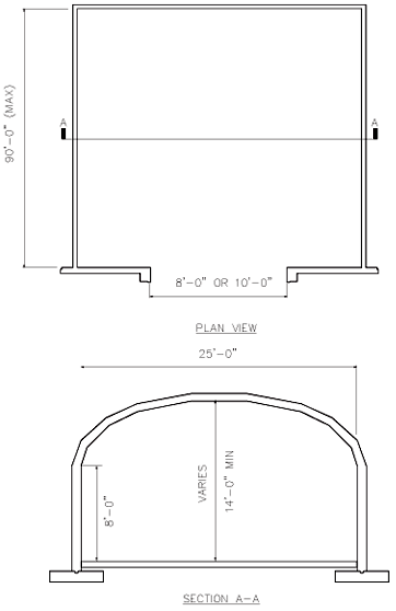 |
USACE Modular Storage Magazine Box–Type Flow–Thru | 421-80-10 | (internal): x 4470mm High | (2) Hinged 12’-1 ¼” Wide x 14’-8 ½” High |
500,000lb |
Approved Files for Use |
USACE Modular Storage Magazine Box–Type European Version | 421-80-13 | (internal): x 4470mm High | (1) Sliding 25' -7 7⁄8" Wide x 16'-1" High |
500,000lb |
Approved Files for Use |
||||
| RC Box Type 'D' (HSILS) |
6448555 through 6448588 Under Navy Review. Contact NAVFAC LANT, Code CI42 |
158'-8" Wide x 50'-0" Long x 13'-8" (Rear) To 15'-10" (Front) High | (3) Sliding 25'-0" Wide x 11'-0" High |
500,000lb |
Approved Files for UseComments/Design ConsiderationUnder Navy Review. Contact NAVFAC LANT, Code CI42 This design is identical to NAVFAC 6448522 through 6448554, Box Type D, except that it incorporates a High Security Integrated Locking System (HSILS). 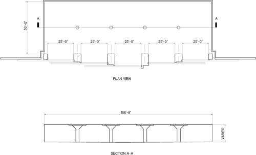 |
||||
| RC Box Type 'F' | 6448589 through 6448621 Under Navy Review. Contact NAVFAC LANT, Code CI42 |
158'-8" Wide x 50'-0" Long x 13'-8" (Rear) To 15'-10" (Front) High | (5) Sliding 16'-0" Wide x 11'-0" High |
500,000lb |
Approved Files for UseDigital DrawingsDocumentationComments/Design ConsiderationUnder Navy Review. Contact NAVFAC LANT, Code CI42 Superseded NAVFAC 1404541 through 1404555. DDESB approval signature of 30 June 87 on drawings. 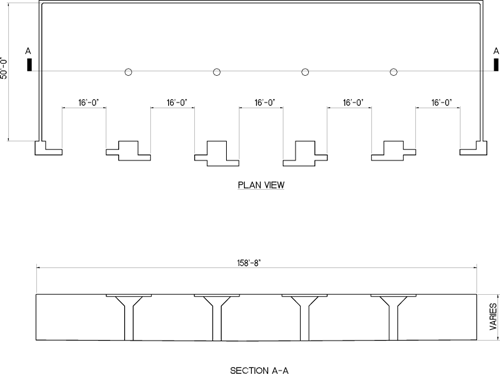 |
||||
| RC Box | High Performance Magazine (HPM) - Concept Design - Drawings not complete | Four cells each 21'-0" Wide x 83'-0" Long x 16'-0" High | Horizontal Rolling Covers Max Opening 21'-0" x 37'-11" | Varies depending on configuration 240,000lb Max. |
Approved Files for UseDigital Drawings (Preliminary Design)DocumentationComments/Design ConsiderationThe HPM design concept was granted DDESB approval as a 7-Bar magazine during the 319th Meeting of 27 January 2000. A preliminary design document, dated 3 July 2001, was completed by NAVFAC. The HPM consist of four separate ordnance storage bays that are treated as independent magazines (i.e., independent MCE). Each storage bay can store up to 30,000 lbs. of net explosive weight. Each bay can optionally be subdivided into two separate storage areas with the use of the "Re-locatable" Modular Wall. Each subdivided storage area can also store up to 30,000 lbs. of net explosive weight, thereby increasing the total storage capacity of the HPM. The separation of the storage bays or subdivided storage areas also allows for the storage of incompatible ordnance in adjacent bays. The maximum storage capacity of a HPM with no subdivided bays is 120,000 lbs. net explosive weight (NEW). If all four bays are subdivided, the maximum storage capacity is 240,000 lbs. NEW. No HPM, other than a test magazine, has been constructed. Construction drawings must be finalized and approved by the DDESB prior to construction start. The HPM design consists of multiple cells, which use non-propagation wall technology to prevent propagation of an incident to adjacent cells. Therefore, the MCE and QD associated with the HPM are based on 60,000 pounds NEW vice the total quantity of explosives stored in all cells of the HPM. Specific mixing and compatibility criteria will apply to storage of ammunition within each cell. As part of the approval, all HD 1.1 and 1.2 AE was placed within five possible HPM Sensitivity Groups. The Joint Hazard Classification System (JHCS) identifies these groups, which define what can be stored together in an HPM. The HPM is not an earth-covered magazine. The HPM is earth-bermed (except for the truck entrance) and moveable RC lids form the roof of each storage cell. The area above the storage cells is enclosed by a lightweight metal panel building, within which is contained the crane that is used for AE movement in the HPM. 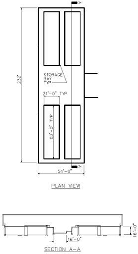 |
||||
| RC Box | Munitionslagerhause (MLH)90B |
165,000lb | ||
Approved Files for UseDocumentationComments/Design ConsiderationNATO explosives safety standards limit this magazine to an HD 1.1 NEQ of 75,000 kg (NEW=165,000 pounds). For siting at U.S installations, where encumbered land is completely within U.S. owned or controlled property, an explosives limit of 250,000 pounds NEW can be used for siting purposes and treat as a non-std ECM. Considered a standard (7-Bar) ECM for sitings involving 165, 000 pounds NEW or less. |
||||
| Steel Oval Arch | Munitionslagerhause (MLH)90S |
165,000lb | ||
Approved Files for UseDocumentationComments/Design ConsiderationNATO explosives safety standards limit this magazine to an HD 1.1 NEQ of 75,000 kg (NEW=165,000 pounds). For sitting at US installations, where encumbered land is completely within US owned or controlled property, an explosives limit of 250,000 pounds NEW can be used for sitting purposes and treat as a non-std ECM. Considered a standard (7-Bar) ECM for sitings involving 165,000 pounds NEW or less. |
||||
| RC Box | Munitionslagerhause (MLH)180B |
25'-1" Wide x 77'-9" Long x 13'-11" High |
(1) 13'-1" Wide x 9'-10" High | 165,000lb |
Approved Files for UseComments/Design ConsiderationNATO explosives safety standards limit this magazine to an HD 1.1 NEQ of 75,000 kg (NEW=165,000 pounds). For siting at U.S installations, where encumbered land is completely within U.S. owned or controlled property, an Explosives limit of 250,000 pounds NEW can be used for siting purposes and treat as a non-std ECM. Considered a standard (7-Bar) ECM for sitings Involving 165,000 pounds NEW or less. 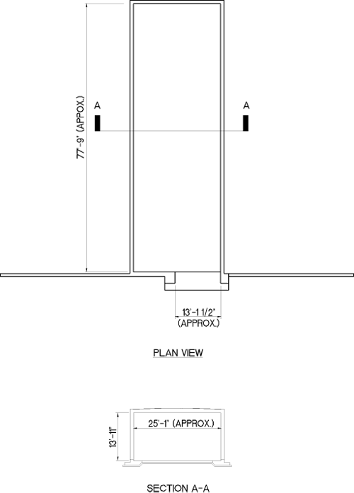 |
||||
| Steel Oval Arch | Munitionslagerhause (MLH)180S |
165,000lb | ||
Approved Files for UseDocumentationComments/Design ConsiderationNATO explosives safety standards limit this magazine to an HD 1.1 NEQ of 75,000 kg (NEW=165,000 pounds). For siting at U.S installations, where encumbered land is completely within U.S owned or controlled property, an explosives limit of 250,000 pounds NEW can be used for siting purposes and treat as a non-std ECM. Considered a standard (7-Bar) ECM for sitings involving 165,000 pounds NEW or less. |
||||
| Single Bay CLWS Navy ECM Standard Drawings | 12905820 through 12905870 | 119'-0" Long x 32'-0" Wide | 32'-0" Wide x 14'-0" High | 500,000 lb |
Approved Files for UseComments/Design ConsiderationThese drawings represent the single bay configuration of the Containerized Long Weapons Storage (CLWS) Navy Earth Covered Magazines, approved by DDESB on 25 July 2024. All new construction of single bay CLWS Magazines will be in accordance with drawings 12905820 through 12905870. |
||||